ASROCK IMB-142 Series Owner's Manual
Browse online or download Owner's Manual for Motherboards ASROCK IMB-142 Series. ASRock IMB-142 Series Owner's Manual User Manual
- Page / 6
- Table of contents
- BOOKMARKS
Summary of Contents
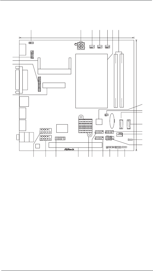
1Motherboard Layout 1 JCF Power Connector (JCF PWR1) 16 Clear CMOS Jumper (CLRCMOS1) 2 ATX 12V Power Connector (ATX12V1) 17 Chassis
2Jumpers Setup The illustration shows how jumpers are setup. When the jumper cap is placed on pins, the jumper is “Short”. If no jumper cap is placed
3Onboard Headers and ConnectorsOnboard headers and connectors are NOT jumpers. Do NOT place jumper caps over these headers and connectors. Placing jum
4Chassis Speaker Header Please connect the chassis (4-pin SPEAKER 1) speaker to this header.(see p.1 No. 17) RESET (Reset Switch): Connec
5ATX 12V Power Connector Please connect an ATX 12V (4-pin ATX12V1) power supply to this connector.(see p.1 No. 2)Serial port Headers Each
61SMBUS DATASMBUS CLKSMBUS Connector (2-pin SMBUS1) (see p.1 No. 9)LVDS Connector Pin Defi nitionPin 1, 2, 3, 4 : Backlight PWRPin 5, 6, 11, 17,
More documents for Motherboards ASROCK IMB-142 Series

Related products and manuals for Motherboards ASROCK IMB-142 Series


 (266 pages)
 (50 pages)
(100 pages)
(163 pages)
(50 pages)
(100 pages)
(163 pages)
 (206 pages)
(163 pages)
(270 pages)
(82 pages)
(149 pages)
(60 pages)
(190 pages)
(206 pages)
(163 pages)
(270 pages)
(82 pages)
(149 pages)
(60 pages)
(190 pages)
© 2020, manymanuals.com. All rights reserved. | 1.195 s |
 Manymanuals.com
 Manymanuals.de
 Manymanuals.fr
 Manymanuals.it
 Manymanuals.pl
 Manymanuals.cz
 Manymanuals.es
 Manymanuals-pt.com
Comments to this Manuals